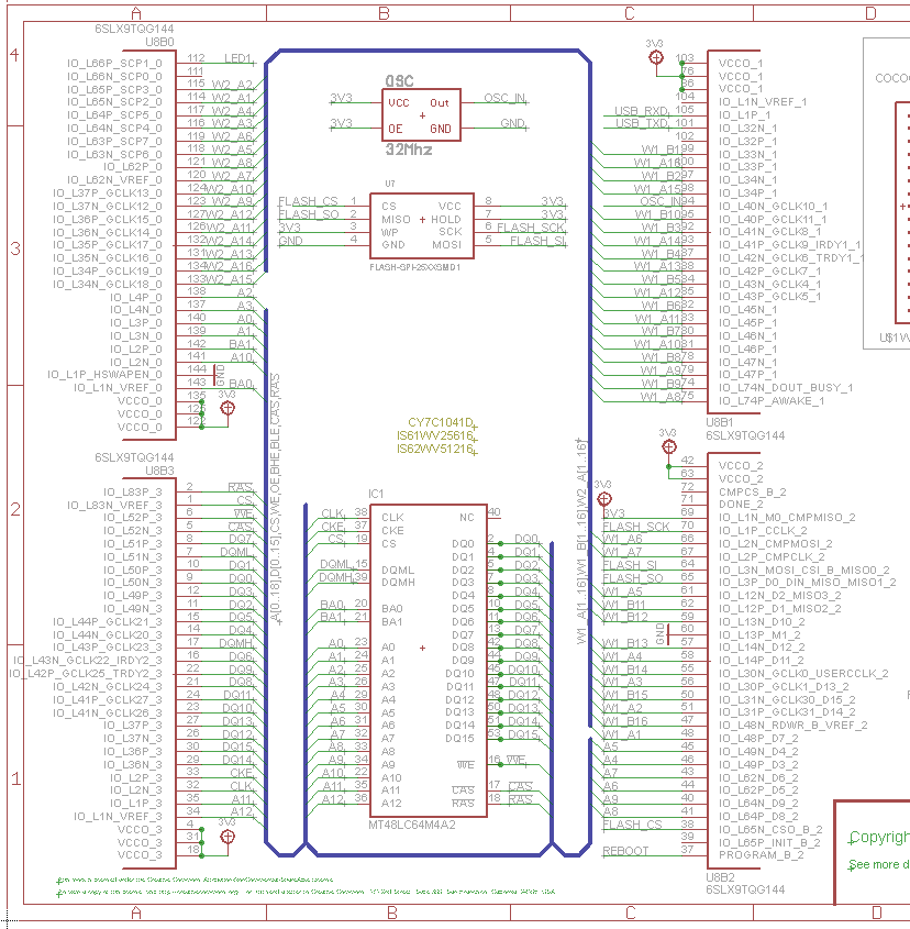
This solves a very specific type of schematic entry where you're connecting tons of digital buses and I/Os. It's pretty tedious and error prone to do this in a schematic editor.
If you're ever done a 50-plus page schematic with a lot of digital parts (FPGAs, micros, etc.), you're stuck using a lot of global port definitions and these are the source of a lot of schematic input errors.
In the above case, it would actually be easier to see where your net is going using the python script as opposed to going through a printed schematic or even a schematic editor.
I know of many schematic types where it would be faster and safer to define the circuit using a script. After all, this is basically what you're doing with an HDL language like Verilog.
This is NOT well suited for analog circuits where you need to understand the circuit topology with lots of discrete components.
Ugh, this hurt my brain. I do Analog and mixed signal designs and the thought of trying to debug a circuit represented as code makes me want to puke. On the other hand, I really find the schematic capture process to be painful so the thought of just writing some copy paste code for creating new parts is pretty appealing. If this thing had some kind of automatic visualization generator it might be kind of fun. Not sure if I'd ditch altium for it though.
As I went through the doc I started to think how cool it would be to put some parametric design features straight into my circuit code. So you could set gain and filter frequencies to be inputs and calculate component values automatically, creating self documenting circuits. But then I saw what they did to the multiplication operator. Yuck, that's super unintuitive:
> r2, r3 = 2*r1
That's how you make two copies of whatever r1 is. But intuitively that statement says, at least to an EE it a circuits guy, that r2 and r3 are resistors with twice the resistance value of whatever r1 is. That is a real problem.
Might be nice for fpga layout design. Tying 400 pins to net names by clicking on each one is tedious and error prone. For everything else I'd really miss the graphical representation of a schematic.
I wouldn't mind using something like this to define bus connections and such, then import the netlist into my schematic editor and have it help me draw the schematic. That would be pretty useful.
I wrote a tool like this for big high-performance test boards at work, the input was a spreadsheet, and I automatically generated (visual) schematics after assigning the netlist using a constraint solver. The analog guys review and debug using the graphical schematics, their design doc, and lab tools. I started the visualization end after thinking about how tumblr packs images onto a webpage pretty well, turns out 2d and 3d shape/box packing is a rich academic field.
I have been "requesting" such a tool for a long time.
Why? Because most of the circuits designed today are mostly digital, and they include IC which are very integrated: lots of functions, and often lots of pins.
So, in the end, you have IC that you cannot represent properly, meaningfully, on a schematic (they have too many pins and many of them can bear a different function depending on configuration); and you spend your time connecting buses or other digital signals... with a non-negligible percentage of error.
What do you use 90% of the time? Straight connections from bus to bus, a few pull-ups/pull-downs here and there, and a good amount of decoupling capacitors, of just 1 or 2 different values, between the same pins. A RC filter on some inputs, a crystal oscillator there. That's almost all, the real analogue circuits parts are
generally small, so even if they are more painful to write and read compared to a schematic, there will still be an overall gain in describing the circuit by text.
Being able to do that (writing those elements and links) in some descriptive language (HDL) would be great. There's a reason why we switched from schematic to HDLs for FPGA / ASIC design. And this reason become more and more meaningful for PCB design too. (Also it would make diffs much easier.)
I had written some syntax example for such HDL, but I suck at compilers and stuff.
I will have a look at this project, even though I fear it won't satisfy me and won't implement what I want. I generally find languages that are piled upon an existing one cumbersome, verbose and unfit for the specific purpose . Especially a descriptive language upon a programming language.
Those schematics though are just throwing everything into a bus... It isn't really differentiating signals at all.
What is the difference between just labeling all the FPGA outputs (which is done here), and then labeling the inputs where they go rather than having the bus line in between?
Or in other words, is this really the best schematic to be comparing against?
>And you would use this with KiCAD -- this just takes the place of eeschema.
That's the point -- if the schematic is just connecting pins to buses and other pins, how is that improved by drawing a rectangle and placing the pins on its perimeter? It can be clearer as a simple textual netlist, or even clearer as a simple textual program that generates the netlist.
_imho_ it is pretty cool, specifically because, writing circuits as code would make the whole thing _composable_ not unlike functions in programming languages.
canonical pcb design e.g. in KiCAD happens in a couple discrete steps:
      - draw the schematic

      - assign footprints to symbolic parts and

      - place them
now, the netlists is what ties all these phases together. an ability to generate this connectivity list programmatically is very useful (imho).
for example a filter circuit generator could take f.e. order, cutoff and type as filter inputs and give you a correct netlist. for your next design, when you need a different filter, changing couple of parameters should be all that is required !
i _suspect_ that we have become inured to seeing circuit diagram as a means (or crutch) of thinking about them.
designing stuff with this should be akin to sketching out block-diagrams where each block is bit of python code that generates the circuit module...
It looks like someone wanted to make an electronics version of OpenSCAD [0]. I agree, it makes more sense integrated into a graphical schematic capture package. There have been a few times when doing large FPGA pinouts that a tool like this could have been useful.
My hobby experience might not be similar to professional usages. In past thought about such tools, considered python for its ease of use and being dynamic. I was leaning towards electron/node.js for native html/css/svg based model generation and display. Also a hybrid approach with point and drag as well as programming facilities generating pcb or components.
It is not a 1-1 comparison but one distant example would be plain text html/css vs frontpage and dreamweaver. Over the time i have seen for a serious work done using plain texts instead of studio based design (may be specific to HTML?).
Couldn't that just be done directly on the netlist, though? I suppose this makes it easier to operate on the netlist, but I imagine there are netlist manipulation libraries that would also accomplish that task.
Think that FPGA used to be programmed with schematic input. I don't think many people would like to go back there. As someone who went through schematic input for FPGAs, I wouldn't :-)
It's a way to write netlists in Python. As someone who uses both Python and does PC board design, this seems useless.
If you want to code something useful in that space, write an open source auto-router. The one for KiCAD no longer works and has IP problems. The author worked for a company that sold an auto-router, and they're unhappy about open source competition.
Or work on KiCAD bugs. KiCAD, which comes from CERN, is open source, but rather buggy. Most of the bugs are UI bugs, which requires good taste in UI to fix.
Yeah, instead of writing a small tool to solve your own problem quickly you ought to spend your time pushing this giant boulder up a hill. Good luck with that pitch!
This is an interesting project. It would be cool to integrate with with a schematic generator. You could then edit the schematic for better logical flow / presentation.
I haven't heard of one for syntax of digital, analog, etc. Quick Google found an analog simulator that ran on LISP machines. Doubt we'll find much more than that given analog is basically math functions on real numbers. Better off using Fortran w/ CSV's if doing old languages. ;)
For KiCAD, initially I believe, the s-exp parser and writer were there just for communicating with an external auto router (Specctra session). But it's taking over more and more.
The footprints have been s-exp for a long time now. I quite like it and am experimenting with mixing in Racket for footprint editing: https://github.com/monostable/footwork
Back in the Stone Age, we used netlists to enter circuit schematics. Then computers evolved to graphical entry; so much nicer. Looks like it has de-evolved back to a net list.
I'm not a super experienced hardware guy, altho I do quite a few bits and bobs, and I always found the graphical entry of schematic... silly.
As a lifelong software developer, entering schematics with little boxes and lines seems roughly equivalent to try to do serious programming using one of these languages where you drag&drop boxes around, used to teach beginners.
Having a way to have a description language for schematics makes a lot of sense; HDL/Verilog exists so you don't have to use the graphical editor for describing your h264 encoder for example. Likewise, Excel source code isn't made in a graphical editor either.
Now I'm not sure the python scripting example given on the page show the potential as it's best as it tries to highlights a bit too much the 'programming' bit; also some sort of 'good practice' would need to evolve; like grouping parts together, labeling, comments etc.
What part of the hardware design process is this for? Is the idea to kick the netlist over the wall and let someone else do the schematic capture and layout? Is there a way to visualize the netlist as a schematic?
I'd say one of the most important parts of a hardware board is having a schematic handy. And even when reverse engineering, you have the PCB and redraw a schematic, not dump everything as a netlist.
Agreed. With traditional tools, I do have a netlist and schematic available for every circuit I work on. I've never reached for the netlist when studying or debugging, it doesn't convey enough information. Sure the netlist technically tells you how it is all connected, but a properly done schematic can give you a deeper understanding of the workings of the device much more quickly due to its layout and utilization of common symbols (instead of part numbers, which are often unhelpful).
All that said, I would love to see this kind of thing as a feature built into a schematic editor.
There's a nugget of a great idea here, the realization that there has to be a better way to describe schematics than drawing them. Unfortunately, most comments seem to be distracted by the trees of what is started here and are missing the forest that is the potential. (Aside: ever stuck on a problem or need to prompt someone else to start talking through a problem, especially in an interview? Ask "what's the worst solution that could be argued to work here? How do we improve it?")
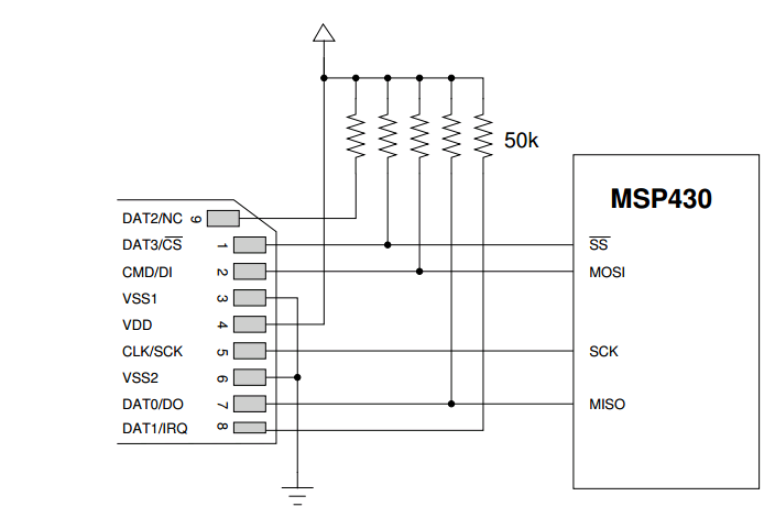
So, what would a more exciting example include? How about sensible "default initializers" so that I don't have to wire up all the power pins, decoupling caps, pull-ups, pull-downs, and no-connects that 98% of the designs for a particular chip need?
  cpu = msp430(vcc=3v3)
  storage = sdcard(vcc=3v3)
  sd_bus = storage.connect(cpu, I2C_FAST) # let cpu and storage negotiate their pins
  # sd_bus is now a list of nets that make up the connection
  utils.apply_pull_ups(sd_bus, 50K)
That's all very possible, computationally, but so much less tedious than drawing it out and so much more descriptive of what I'm actually trying to achieve. As a bonus, it has properties programmers forget so many other people's tools don't: it's good for line-based diff, search/replace, and source control.
  loop_filter = utils.third_order_bandpass(freq_min, freq_max, RC_ONLY)
  freqgen = adf4350(vcc=3v3, cp_filter=loop_filter) # boom, all sensible defaults
  for pin, color in zip(freqgen[LD, CE, LE], ('green', 'red', 'yellow')):
      pin.net.connect(status_led(color=color, brightness=30mcd))
      # let the computer work out your resistor value
  freqgen[RFOUT_A].connect(BNC(50Ohm, SINGLE_ENDED))
  freqgen[RFOUT_B].connect(BNC(50Ohm, SINGLE_ENDED))
  # let the computer work out that it terminates the complementary output
The linked project isn't nearly at this point, but I consider it in the same spirit. We have to go through the awkward solutions while we iterate towards a great one, I would say.
One of the pains about larger embedded designs, is that while newer processors/microcontrollers have so many different peripherals and ways to use them, there are just as many constraints about which functions can go to which pins, how each peripheral is clocked, etc..
Their tool is similar to what you mentioned, in that you tell it what peripherals you want to use, and how, if you have any pins you need to lock down, etc. It will then solve these constraints and give you a pinout and clock setup that will work, along with boilerplate code to get you started.
I would love to see an open-source effort in this space...basically a parametric framework / boilerplate generation for embedded systems designs (hardware and software).
If you're ever done a 50-plus page schematic with a lot of digital parts (FPGAs, micros, etc.), you're stuck using a lot of global port definitions and these are the source of a lot of schematic input errors.
In the above case, it would actually be easier to see where your net is going using the python script as opposed to going through a printed schematic or even a schematic editor.
I know of many schematic types where it would be faster and safer to define the circuit using a script. After all, this is basically what you're doing with an HDL language like Verilog.
This is NOT well suited for analog circuits where you need to understand the circuit topology with lots of discrete components.